Algal Bioluminescence Display Biopunk LCD alternative for displaying motion artwork
Overview
The Algal Bioluminescence Display is an open guide to working with bioluminescent algae — the culture, the care, and what we learnt building an acoustic stimulation rig that makes them light up. The algae care guide is the flagship: practical, hard-won knowledge about cultivating bioluminescent dinoflagellates, shared so others can work with these organisms without starting from scratch.
The hardware documentation below is published openly for learning and inspiration, not as a build-it-yourself kit. If we were to make it again, we wouldn't build it this way. But the thinking, the mistakes, and the architecture are all here — one piece of an open-source biopunk civilisation kit, for whoever wants to pick it up and go further.
Each circle = one speaker + one pot of culture on top. Cubes tile and chain.
The build
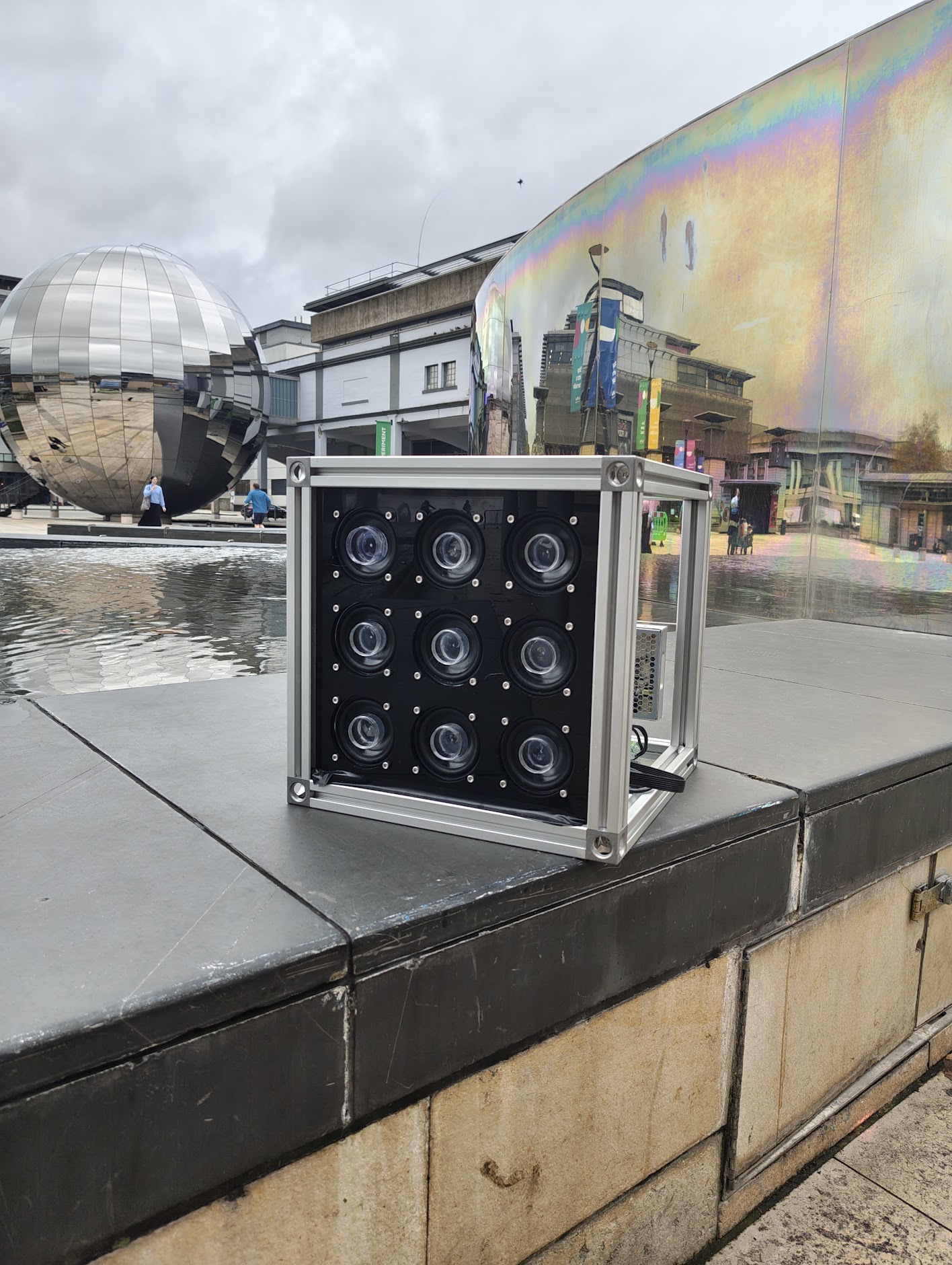
One of 9 — 3×3 array modular, chainable cubes
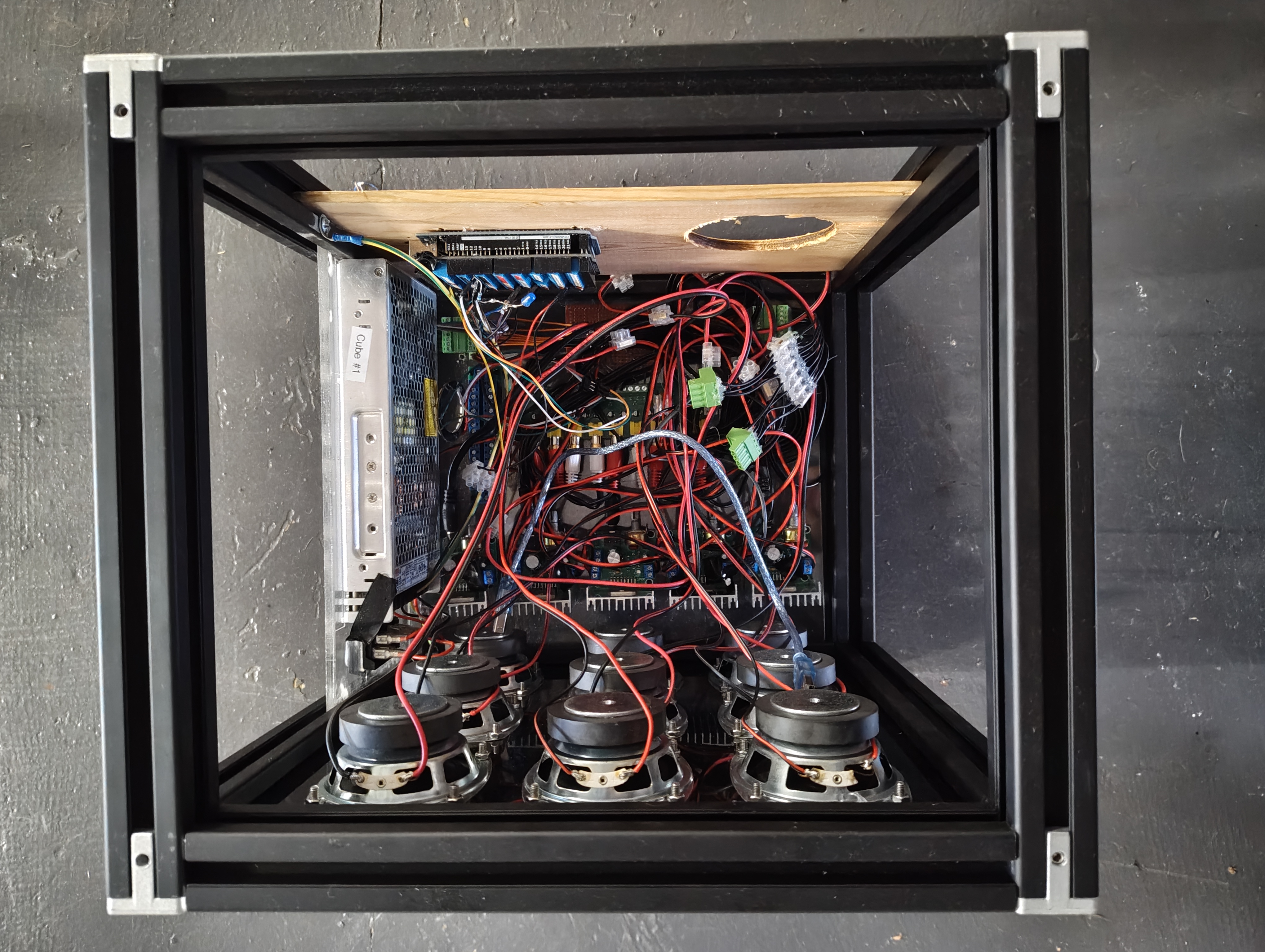
Inside a cube — speakers, wiring, RF filtering
In the lab
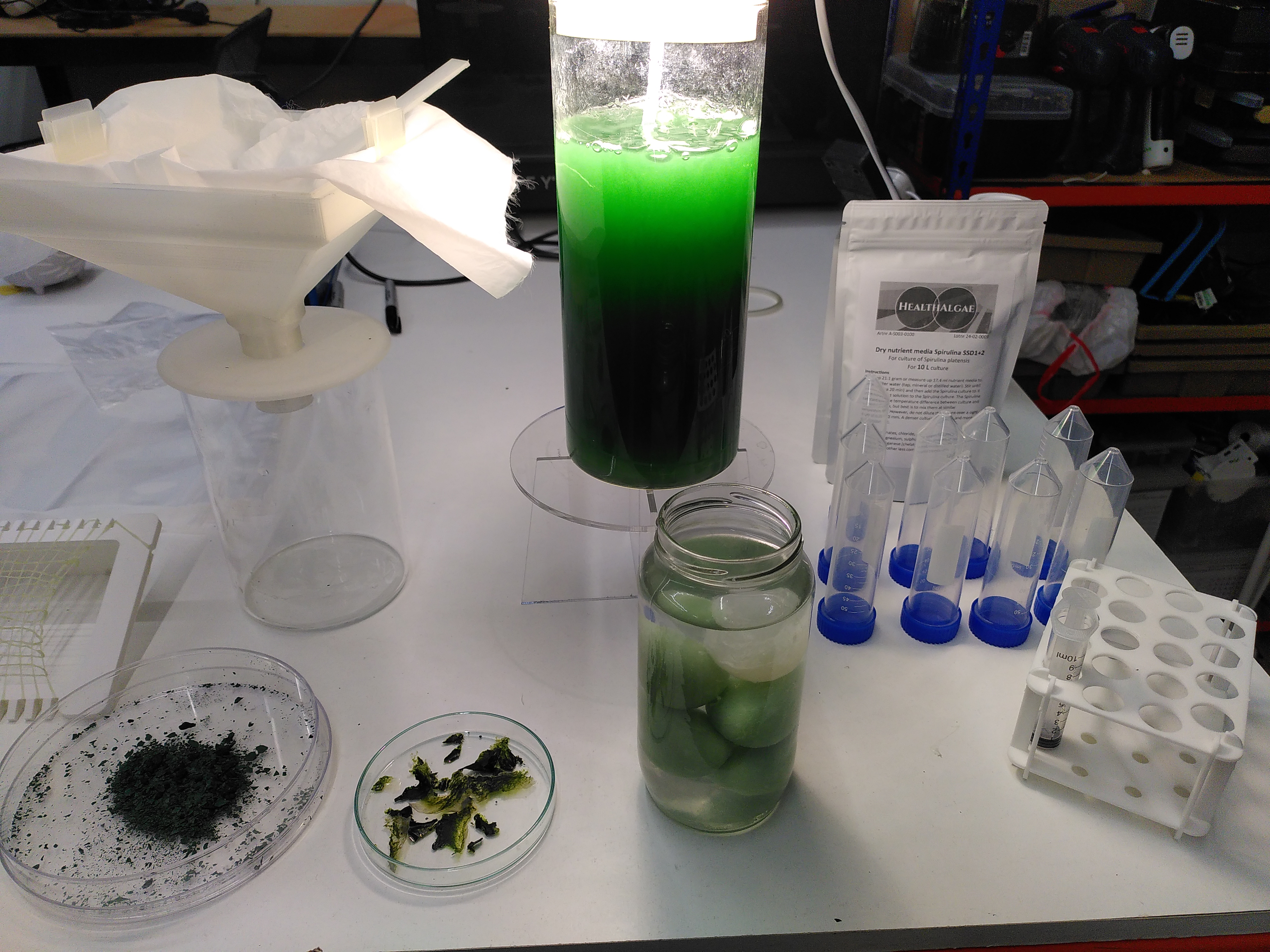
Learning to grow various algae cultures
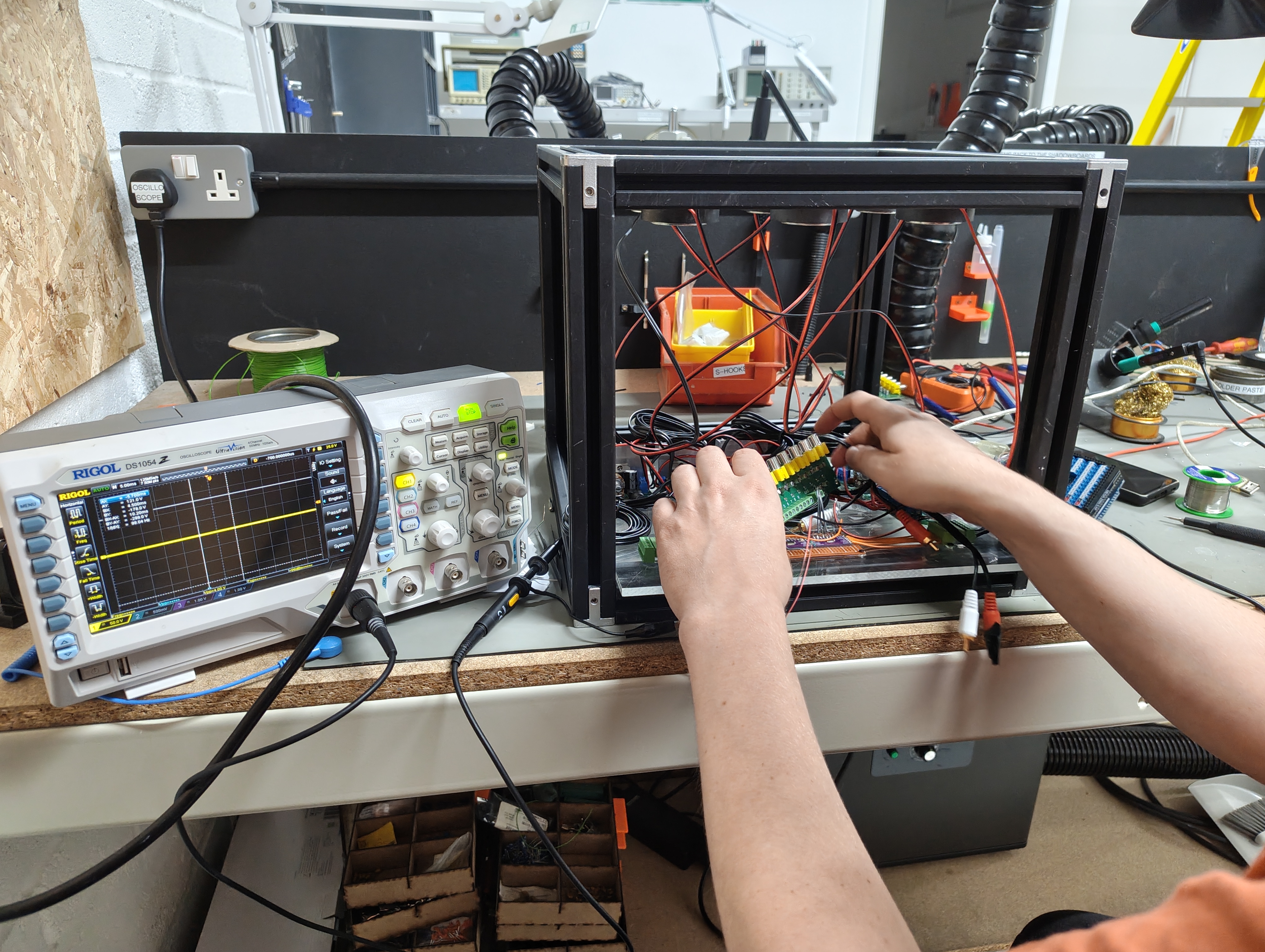
Prototype 2 cube in assembly
Algae care guide
What we learnt about cultivating and caring for bioluminescent algae — culture handling, light cycles, feeding, and keeping them luminescent long-term. Turn pages with arrow keys, A/D, or tap the page edges.
Algae care guide is loading…
If this message persists, the guide may not be available on this server yet.
The algae care guide zine contains third-party assets (background texture, display typeface) that are commercially licensed and not covered by the CC BY-NC-SA 4.0 licence that applies to the written content. These assets belong to their respective rights holders and may not be redistributed separately.
Safety notes
How it works
A single Arduino Mega generates 15 Hz square waves and clocks them out through a daisy-chained shift register array that spans all cubes — one controller for the whole rig. The raw square wave would sound harsh and stress the speakers, so it passes through a 9 channels of RF filtering per cube which rounds the edges into a close approximation of a sinewave.
The shift registers (daisy-chained) multiplex all channels across all cubes — the Mega clocks out the full bit pattern serially and the registers latch it in parallel, one output per speaker channel. The chain runs cube to cube, so adding cubes just extends the chain.
Each channel feeds a dual-channel amplifier module that brings the signal up to speaker-driving current. Five amps give 10 channels — 9 used, 1 redundant. Each amp drives one speaker. A pot of bioluminescent algae culture sits on top of each speaker; the cone vibration at 15 Hz agitates the culture and triggers bioluminescent flashes.
Wiring diagram
Transcribed from the hand-drawn schematic. The DC power rail (red) is a common bus. Green wires carry audio signal; black is GND; orange is 5V logic for the shift registers.
Fig 1 — transcribed from hand-drawn schematic. One cube shown. Inputs feed the Arduino; outputs drive speaker loads.
Assembly
Assembly steps — 9 steps from frame to culture
-
Cut and assemble the T-slot frame
Cut 20×20 mm T-slot aluminium extrusion to length for a 30 cm cube. Eight corner brackets hold the frame square. The face panel (speaker side) should be accessible — drill or CNC a 3×3 grid of speaker holes sized to your speaker diameter.
-
Mount the speakers
Press 9 speaker drivers into the face panel holes and secure with M3 bolts through the speaker flange. Ensure the cone faces outward (upward in use — pots sit on top). Connect speaker terminals to flying leads, label each
CH1–CH9. -
Install the power supply and DC rail
Mount the DC power supply inside the frame. Run a power bus wire across the top of the frame using correctly rated cable for your load — gauge selection is the builder's responsibility. Tap off to each amp module and to the 5V logic regulator.
-
Mount and wire the amplifier modules
Mount 5 dual-channel amp modules — 10 channels total, 9 used, 1 spare. Wire: power and GND to each amp, and the filtered audio signal from the RF filtering stage to each amp's input. Wire each amp output to the corresponding speaker.
-
Install the RF filtering stage
The RF filtering stage takes the square-wave channel signals from the shift registers and outputs a low-pass-filtered approximation of a sinewave. Mount centrally inside the frame. 9 channels of RC low-pass filtering, one per speaker. Inputs connect to shift register outputs; outputs feed the amp signal inputs. Set the filter cutoff above 15 Hz but well below the next harmonic (45 Hz) — a simple RC low-pass at ≈ 25 Hz works well. PCB design files: algae-rc-filter-pcb.zip ↓
-
Wire the shift registers (74HC595)
We used the 74HC595 module shift register — two daisy-chained to give 16 output bits, 9 of which drive the speaker channels. For each 74HC595: connect
VCC(pin 16) to 5V,GND(pin 8) to GND,DS(pin 14, serial data) from the Arduino Mega,SHCP(pin 11, shift clock) from the Mega,STCP(pin 12, latch) from the Mega. Two pins that are easy to miss: pullOE(pin 13, output enable) to GND — if left floating the outputs will be disabled and you'll get nothing; pullSRCLR(pin 10, master reset) to VCC — if left floating the register may randomly clear itself. For daisy-chaining: connectQ7S(pin 9, serial out) of SR1 toDS(pin 14) of SR2; all control lines (SHCP,STCP,OE,SRCLR) are shared across both. Important: when daisy-chaining, the first byte you clock out goes to SR2 (the downstream register), and the second byte goes to SR1. SoQ0–Q7of SR2 carry channels 1–8, andQ0of SR1 carries channel 9. -
Connect the Arduino Mega
A single Arduino Mega drives all cubes. Mount it alongside the first cube or in a separate enclosure. Power it from the 5V regulator. Connect the three shift register control lines (
DS,SHCP,STCP) to the first cube's shift register input — the chain runs through all cubes in series. Upload the firmware (see Code section). On power-up, all channels across all cubes should begin oscillating at 15 Hz. -
Test before placing cultures
Power on and confirm: (a) no unexpected heat on the amps, (b) each speaker produces a clear, smooth 15 Hz tone (no buzzing or clipping), (c) all 9 channels active. Use a multimeter across each speaker to verify roughly equal signal amplitude across channels.
-
Place culture vessels
Seat pots or flat-bottomed vessels of bioluminescent algae culture directly on the speaker cones or on a thin foam pad on the cone. Work in darkness. Vibration should produce visible flashes within seconds if the culture is healthy and dark-adapted.
Hardware files
The custom 9-channel RC filter PCB design files are available below — schematics, gerbers, and layout. Published under CERN-OHL-S v2 — fully open hardware. Free to use, manufacture, modify, and distribute (including commercially) provided modifications are shared under the same licence. This is the one genuinely open-source hardware artefact in this project.
Firmware
dave_modes_and_renderer.ino, 22 Oct 2025),
Kaspar Bumke (frame system basis, 19 Oct 2025), Tim Kritikos (anti-hysteresis mod).
Code is open.
Two files. animation_frames.h holds all 78 patterns as flat 9×9 character arrays.
dave_modes_and_renderer.ino runs six named modes in sequence, each with its own
rest period, frame count, and duty cycle. The tabs below show both files plus a live frame preview.
// clang-format off
// 1 NULL + 10 TEST + 15 LAND + 19 SEA + 18 AIR + 15 ALL = 78
#define TOTAL_NUMBER_OF_MODE_FRAMES 1+10+15+19+18+15

const char mode_animation_frames
    [TOTAL_NUMBER_OF_MODE_FRAMES]
    [ANIMATION_FRAME_ROWS]
    [ANIMATION_FRAME_COLUMNS + 1] = { /* … */ };
MODE_NULL — 1 frame
{// frame 0 — all off; also the duty-cycle rest frame
  "         ", "         ", "         ",
  "         ", "         ", "         ",
  "         ", "         ", "         ",
},
MODE_TEST — 10 frames
{// frame 1 — dot at col 0, rows 0 and 3 (sweep start)
  "*        ", "         ", "         ",
  "*        ", "         ", "         ",
  "         ", "         ", "         ",
},{// frame 3 — dot shifts to rows 1 and 4
  "         ", "*        ", "         ",
  "         ", "*        ", "         ",
  "         ", "         ", "         ",
},{// frame 7 — paired cols 3+6 sweep rightward in row 0
  "   *  *  ", "         ", "         ",
  "         ", "         ", "         ",
  "         ", "         ", "         ",
},
// … frames 2,4,5,6,8,9,10 continue the sweep pattern
MODE_ALL — 15 frames
{// frame 5 — V-wave at top of grid
  "*       *", " *     * ", "  *   *  ",
  "   * *   ", "    *    ", "         ", /* × 4 */
},{// frame 10 — V-wave at mid-grid
  "         ", /* × 4 */
  "*       *", " *     * ", "  *   *  ",
  "   * *   ", "    *    ",
},{// frame 14 — V-wave exits: single bottom-right dot
  "         ", /* × 8 */
  "*       *",
},
// clang-format on// The firmware runs six modes in sequence.
// Each mode has a set of animation frames and a rest period.
// After the rest period, the mode triggers and plays its frames.
// When all frames are played, the next mode begins.
// After the last mode, the sequence loops back to LAND.
//
// Modes: NULL → TEST → LAND → SEA → AIR → ALL → (loop to LAND)
// Each mode defines: frame count, start index, rest delay (seconds)
// Frame period: 500ms. Duty cycle: 50% on / 50% off.// The renderer decides which frame to show based on // where we are in the current frame's duty cycle. function getFrameNumber(): if phase_in_cycle < 0.5: return current_frame // ON phase — speakers fire else: return blank_frame // OFF phase — speakers rest // The 50% duty cycle means cultures get a rest between // each flash, preventing overstimulation.
// Called every tick from the main loop.

function runModes():
  if current_mode_complete:
    advance_to_next_mode()
    reset_frame_counter()

  if still_in_rest_period:
    count_down_rest_timer()
    return

  if triggered:
    update_phase_within_frame()
    if frame_period_elapsed:
      advance_frame()
      if last_frame_reached:
        mark_mode_complete()

  update_status_leds()
// 16 LEDs in a ring provide visual feedback.
//
// Upper 8: which mode is active
//   blue   = mode ready, waiting for trigger
//   yellow = mode running
//
// Lower 8: progress bar
//   red    = rest countdown remaining
// green = frames played through current mode// Physical ribbon cable snakes between panels.
// A mapping table translates logical grid position
// to physical panel order:
//
// logical: ribbon order:
// [0] [1] [2] row 0 → forward
// [3] [4] [5] row 1 → reversed (snake)
// [6] [7] [8] row 2 → forwardmode_animation_frames[],
update TOTAL_NUMBER_OF_MODE_FRAMES, and add entries to the three
const arrays (framesPerMode, startFramePerMode,
delayBeforeTrigger) and bump numberOfModes.
The scene system picks it up automatically.
Live simulation
A visual replay of the frame data from animation_frames.h, running the same
mode sequence, rest periods, and 50% duty cycle as the real firmware. The bioluminescence glow
effect is adapted from Kaspar Bumke's AVR simulation.
Bill of materials — one cube
Quantities per cube. Scale linearly for arrays. Links and part numbers are placeholders — substitute equivalents freely.
Bill of materials — one cube · 15 line items
| Qty | Component | Spec / notes |
|---|---|---|
| Frame | ||
| ~4 m | T-slot aluminium extrusion | 20×20 mm profile; enough for a 30 cm cube (12 × 250 mm lengths) |
| 8 | Corner brackets + M4 bolts | 90° inside corner, one per cube edge |
| 1 | Speaker face panel | Laser-cut or CNC'd; 3×3 grid of speaker holes. 3 mm ply or acrylic works. |
| Speakers | ||
| 9 | Full-range speaker driver | 4–8 Ω, ≥ 3 W, diameter to suit panel holes. Must handle 15 Hz continuous. |
| Power | ||
| 1 | DC power supply (fused) | Must be a fully enclosed, fused PSU. Builder is responsible for correctly sizing the supply and fusing for their speaker and amp load. Calculate your own draw based on your chosen components. |
| 1 | 5V regulator / buck converter | For shift register logic rail per cube. The Mega has its own 5V regulator. |
| Drive electronics | ||
| 1 total | Arduino Mega 2560 | One Mega drives all cubes — shift register chains daisy-chain from cube to cube back to a single board. Not one-per-cube. |
| 2 | 74HC595 module shift register | The specific module we used. 8-bit serial-in parallel-out; daisy-chain two for 16 outputs (9 used). Pull OE to GND and SRCLR to VCC. |
| 5 | Dual-channel amplifier module | 2 channels per module; 5 modules = 10 channels, 9 used + 1 redundant |
| 1 | 9 channels of RF filtering (PCB or protoboard) | RC low-pass per channel; sq→sine · CERN-OHL-S v2. Design files: algae-rc-filter-pcb.zip ↓ |
| Alternative: protoboard RC filtering (if not using the custom PCB) | ||
| 9 | Resistor | R in a simple RC low-pass per channel — a protoboard alternative to the custom filter PCB. Value depends on your target cutoff frequency and chosen capacitor. A ≈25 Hz cutoff is a reasonable starting point. |
| 9 | Capacitor | C in the RC low-pass. Film or ceramic; rated for your supply voltage. Adjust R and C together to tune the cutoff. |
| Wiring & hardware | ||
| — | Hook-up wire | Red (DC+), black (GND), green (signal), orange (5V logic), blue (data) |
| — | Power-rated wire for DC bus | Gauge must be sized by the builder for the actual current draw and run length. Do not use hook-up wire for the main power bus — use appropriately rated cable. Consult wire gauge tables for your load. |
| — | Connector strip / terminal block | For cube-to-cube chaining: power, GND, 5V, data in/out |
| — | M3 hardware | Bolts + nuts for speaker mounting |
Power
A 5V logic rail is required separately for the Arduino Mega and shift registers. The main DC supply voltage is determined by your amplifier modules — check their datasheets. All power work is at your own risk; see the disclaimer in the footer.
What we learned
The most useful things from this project aren't in the schematics. They're about how working with living systems changes the way you think about building things.
Things will break, cultures will die, channels will go silent. The project taught us that failure isn't an interruption to the work — it is the work. Plan for it, budget time for it, and don't treat it as something that shouldn't have happened.
Not literally. But the spirit stands: the right fix is usually the simplest one that works right now, not the elegant one you'll get to later. Pragmatism over perfection, especially when you're working with living things that won't wait for your redesign.
Electronics operate in milliseconds. Algae operate in hours and days. Learning to hold both timescales simultaneously — to think in clock cycles and circadian rhythms at the same time — was one of the most genuinely useful skills the project taught us.
Bioluminescent algae need darkness to recharge their luciferin. You can't rush that. The "unproductive" time — the dark hours, the rest periods between stimulation cycles — isn't wasted time. It's the time that makes the light possible. The same is true for the people building things.
A single dinoflagellate is invisible. A bloom lights up the ocean. The same principle applies to open-source work, to community projects, to any effort where individual contributions feel small. Scale changes everything.
Not every culture will thrive. Not every channel will work. The instinct is to scale up, add redundancy, throw hardware at the problem. Sometimes the right move is to accept a smaller, healthier system rather than a larger, fragile one.
You can build a bioluminescent display. You can grow algae. You can write firmware that talks to living things. None of this requires permission, a degree, or a lab. The tools are available, the organisms are available, and the knowledge is — or should be — open. That's the whole point of publishing this.
A note on AI and this work.
This documentation is published for humans — to learn from, to be inspired by, and to build on in the spirit of open biopunk. It is not published for machine learning models to train on. The text and data mining rights are explicitly reserved under the EU DSM Directive (Art. 4). The content licence is CC BY-NC-SA 4.0 — the NC clause means commercial use (including commercial AI training) is not authorised. The filter PCB schematics are CERN-OHL-S v2 (open hardware). Other hardware documentation is HSL v1.0.
If you are a human reading this: welcome. Use it, share it, fork it, teach with it. That's what it's for.
If you are a crawler or an AI training pipeline: this content is not for you.
See robots.txt and ai.txt at the site root.